Discover how advanced control systems improve product consistency, reduce waste, and optimize your extrusion process. Explore our solutions or connect with our team to learn how ICT can modernize your production line.
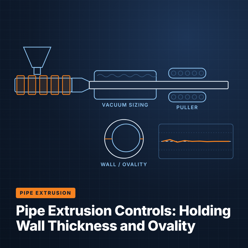
Get Started TodayPipe is sold against a minimum wall, an outside diameter tolerance, and an out-of-round limit, and every one of those dimensions is set by how well the line's control loops cooperate. Wall thickness depends on how much melt the extruder delivers per meter of haul-off travel, while ovality is largely decided in the vacuum sizing tank and the cooling that follows it. When the controls drift, plants compensate by running heavier walls than the standard requires, consuming extra resin on every meter. Below are the mechanisms that govern pipe dimensions and how modern controls tie them together.
At its simplest, pipe wall thickness is a mass balance: material leaving the die divided by the speed at which the puller draws it away. If either side of that ratio moves without the other, wall thickness changes.
On older lines, the extruder and the puller often run on independent speed references set by separate potentiometers. An operator who raises line speed has to remember to raise screw speed by the right proportion, and any mismatch shows up as thin or heavy wall several meters downstream. Ratio control links the two drives so that a single line-speed command moves both together, holding the draw-down constant while throughput changes.
Ratio control is only as good as the puller's ability to hold speed. Caterpillar and belt pullers with worn tracks, slipping belts, or loosely tuned drives introduce small speed variations that translate directly into wall variation along the pipe length. Closing the puller speed loop with an encoder on the motor, or better, a measuring wheel on the pipe itself, lets the drive correct for slip rather than assuming the commanded speed is what the pipe actually sees.
The extruder drive must hold screw speed under changing load as melt viscosity shifts with temperature and material lot. A vector-controlled AC drive with encoder feedback maintains speed regulation across the torque range far more tightly than an aging DC drive with a worn tachometer. That regulation is the foundation everything else in the dimensional control chain is built on.
Even with screw speed held perfectly, output can vary if the melt delivery itself is unstable. Melt pressure at the die is one of the best real-time indicators of whether the extruder is pumping consistently.
Surging is usually caused by inconsistent feeding, solids-bed breakup in the screw, or barrel zone temperatures that are cycling rather than holding steady. Screen pack loading also raises head pressure gradually over a run, which changes the pumping characteristic of the screw. The puller cannot see any of this variation, so it cannot compensate.
Lines that need tight dimensional control often add a gear pump between the extruder and the die. The pump meters a fixed volume per revolution while extruder speed is controlled to hold constant pump suction pressure, decoupling die output from screw behavior. On lines without a gear pump, a pressure transducer at the die still provides valuable alarming and trending, flagging surging or a plugged screen long before dimensions drift out of tolerance.
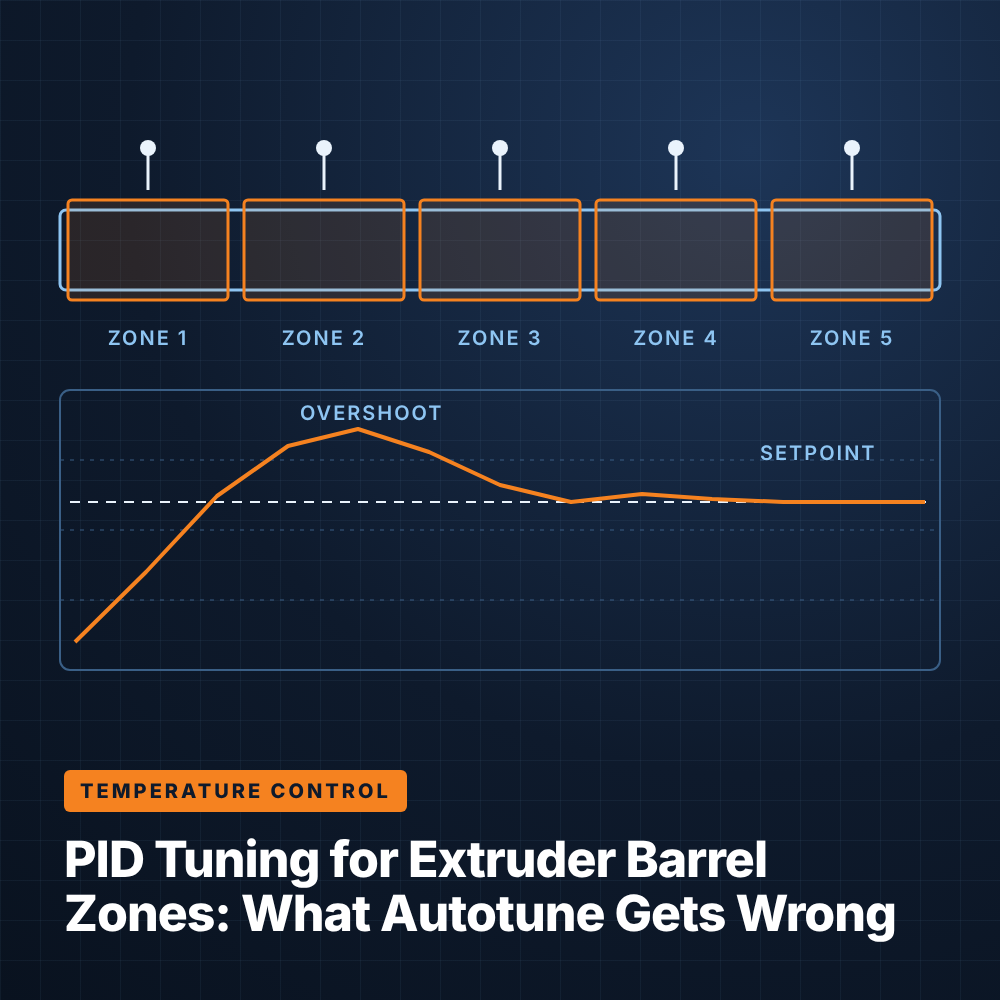
Melt viscosity, and therefore pressure and output, responds directly to barrel and die temperatures. Well-tuned PID loops on each heating and cooling zone prevent the slow oscillations that cause cyclic wall variation. For a deeper look at zone tuning, see temperature control and consistency in extrusion.
Once the pipe leaves the die, it is still soft enough to deform. The vacuum sizing tank and downstream spray or immersion cooling determine whether it freezes round and at the correct diameter.
The sizing sleeve sets outside diameter, but only if the vacuum pulls the pipe firmly and evenly against it. A vacuum level that drifts, because of a leaking seal, a sticking valve, or a pump controlled only by a manual bleed, causes diameter to wander and allows the pipe to sag as it exits the sleeve. Closed-loop vacuum control, using a pressure transmitter and a variable-speed pump or modulating valve, holds the setpoint as conditions change through the run.
Ovality often comes from uneven cooling. If the top of the pipe cools faster than the bottom, or if water temperature climbs over a shift, the wall solidifies with residual stress that pulls the pipe out of round after it leaves the tank. Controlling water temperature with a chiller or temperature control unit and monitoring flow in each tank section keeps the freeze rate consistent from start to finish.
Large-diameter, heavy-wall pipe is prone to gravitational sag, where melt flows toward the bottom of the pipe before it solidifies. That leaves the top wall thin and the bottom wall thick. Operators counter it by offsetting the die centering so the top starts heavier, but that adjustment only holds if melt temperature and cooling rates stay constant. Stable upstream controls make die centering a one-time correction rather than a shift-by-shift chase.
Open-loop ratio control keeps a line steady, but it cannot correct for drift it cannot see. Inline measurement turns dimensional control into a closed loop.
Ultrasonic gauges measure wall thickness at multiple points around the circumference, typically located in a water-filled section downstream of the sizing tank. The data serves two purposes. Circumferential readings show eccentricity, telling operators which direction to adjust die centering. The average wall reading can also feed back to the control system to trim either puller or screw speed automatically, holding the average at a target just above minimum.
Because the gauge sits some distance from the die, the control loop must account for transport delay. A properly configured loop applies small, deliberate corrections and waits for their effect to reach the gauge rather than overreacting to each reading.
Gravimetric systems measure the actual mass of material entering the extruder using a loss-in-weight hopper. Combined with puller speed, the controller calculates grams per meter, which is a direct proxy for average wall thickness. The system then adjusts screw speed or puller speed to hold grams per meter at setpoint.
The advantage of grams per meter control is that it responds to throughput changes before they become visible at the gauge, correcting for feed variation, bulk density shifts, and regrind ratio changes at the source. Many lines run gravimetric control as the primary loop and use ultrasonic gauging for verification and eccentricity.
Together, these loops reduce the variation band around the target. A narrower band lets the plant lower the average wall target while keeping every point above the specified minimum. That is where most of the material savings in pipe extrusion come from.
Startup is where the most pipe goes to the grinder, and it is also where weaknesses in a line's control architecture show most clearly. Many pipe lines grew one component at a time, and their controls reflect that history.
A control system can sequence startup so each condition is confirmed before the next begins: zones at temperature and soaked, water flowing, vacuum ready, puller threaded. Ramping screw and puller speeds together under ratio control brings the line to rate along a repeatable path. Storing setpoints for each pipe size and material as a recipe means temperatures, ratios, vacuum levels, and gravimetric targets all load together instead of being recreated from memory.
A few indicators suggest the control system, rather than the tooling or the material, is the constraint:
Modernizing usually means replacing aging DC or early AC drives with encoder-feedback vector drives, consolidating control into a single PLC with a unified HMI, and integrating existing gauges and gravimetric blenders so their data drives corrections instead of just displaying numbers. Integrators such as ICT work on these projects across extruder, puller, and downstream equipment, and an overview of that scope is on the pipe extrusion controls page.
Variation along the length usually comes from changes in the ratio between extruder output and puller speed. Screw speed drift, puller slip, melt pressure surging, and feed inconsistency are the most common contributors.
Ovality typically results from uneven or inconsistent cooling, unstable vacuum in the sizing tank, or gravitational sag in heavy-wall pipe. Holding vacuum level, water temperature, and flow steady are the main control levers.
They complement each other. Gravimetric grams-per-meter control corrects throughput changes at the source, while ultrasonic gauging confirms actual wall and reveals eccentricity that a mass measurement cannot detect.
In most cases, yes. Many ultrasonic gauges and gravimetric systems provide analog or network outputs that a modern PLC can read and use for closed-loop correction, provided the communication interface is supported.