Discover how advanced control systems improve product consistency, reduce waste, and optimize your extrusion process. Explore our solutions or connect with our team to learn how ICT can modernize your production line.
Get Started TodayFeeding is where an extrusion process begins, and errors introduced at the throat carry through to every downstream measurement. Gravimetric feeders and blenders measure material by weight rather than volume, giving the control system a direct, real-time view of throughput. The real value appears when that information is tied into the extruder and line controls instead of living on a standalone panel. This article explains how feeding methods differ, how ratio and throughput control work, and what integration looks like in practice.
All feeders move material, but they differ in what they actually control. Understanding that difference explains why gravimetric systems have become standard on lines where material cost and consistency matter.
A volumetric feeder delivers a set volume per unit time, typically by running an auger or disc at a fixed speed. It is simple and inexpensive, but it assumes bulk density is constant. In reality, bulk density varies with pellet size, regrind content, moisture and how full the hopper is. When density shifts, the mass delivered shifts with it, and the feeder has no way to know.
Volumetric feeding can work acceptably for single-component processes with consistent virgin resin, but it requires periodic manual catch-weighing to verify rates and recalibrate.
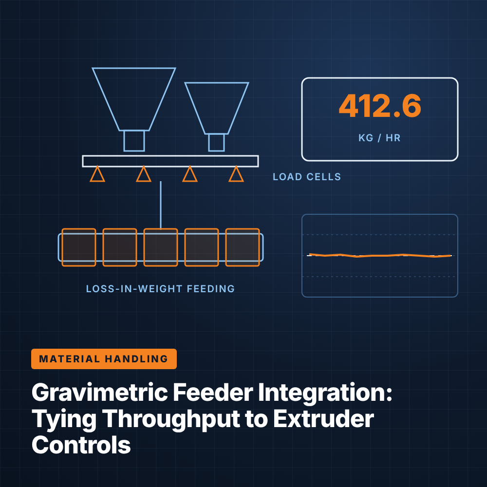
A gravimetric feeder measures the weight of material dispensed and adjusts its metering device to hit a mass-rate setpoint. In a loss-in-weight design, the entire feeder, including hopper and screw, sits on load cells. The controller watches weight decrease over time, calculates the actual feed rate and trims auger speed to match the target in kilograms per hour.
Because the feeder corrects for density changes automatically, it maintains an accurate mass rate even as materials vary. This is especially important for expensive additives, colorants and fillers, where overfeeding wastes money and underfeeding risks product quality.
Batch blenders weigh each component sequentially into a weigh bin, then dump the batch into a mixing chamber that feeds the extruder throat. They do not meter continuously, but they deliver an accurately proportioned blend and can calculate throughput from the rate at which batches are consumed. They are common on film, sheet and profile lines running multiple components.
Most extrusion formulations involve more than one material. Keeping the proportions right as total throughput changes is the job of ratio control.
In a continuous multi-feeder system, a master throughput setpoint is distributed to each feeder as a percentage of the total. If the formulation calls for a certain percentage of masterbatch, the masterbatch feeder's setpoint is calculated from the total rate and adjusted automatically whenever the total changes. Each feeder runs its own loss-in-weight loop, but they share a common reference so ratios hold during speed changes.
Batch blenders achieve ratio control differently, by weighing each component to its target fraction of every batch and correcting the next dispense for any error in the previous one.
Storing formulations as recipes in the line control system means component ratios, throughput and extruder settings can be loaded together. This reduces the chance of an operator setting a correct extruder profile with an outdated blend ratio, or vice versa. Recipe-driven changeovers also produce a record of what was run, which supports traceability and troubleshooting.
Many lines run gravimetric equipment from its own controller, with operators entering setpoints at the feeder and the extruder separately. That works, but it leaves useful information stranded.
In standalone mode, the feeder controller holds its own throughput or ratio setpoints and may send a simple analog or discrete signal to the extruder. Operators must coordinate changes manually, and alarms may appear only on the feeder display. When the extruder speed changes, the feeder does not necessarily follow, and when the feeder runs low, the extruder may not know until output drops.
Modern gravimetric controllers typically support industrial networks such as EtherNet/IP, PROFINET or Modbus TCP. Connecting them to the line PLC allows setpoints, actual rates, component ratios, hopper levels and alarms to be exchanged continuously. The HMI can show feeding data alongside temperatures, pressures and drive loads, and the PLC can coordinate feeder and extruder responses during starts, stops and rate changes.
Integration also means a single recipe can drive both the extruder and the feeding system. Data from the feeders becomes available for trending, production reporting and remote monitoring without separate software.
Integration requires clear ownership of each setpoint. The design should define whether the PLC or the feeder controller is the master for throughput, what happens if communication is lost, and how the system falls back to a safe operating mode. A communication watchdog that alarms and holds the last valid setpoint is a common approach.
Once the control system knows exactly how many kilograms per hour are entering the extruder, it can close loops that were not possible with volumetric feeding.
In starve-fed or gravimetrically controlled systems, mass throughput becomes a directly controlled variable. The operator sets a target in kilograms per hour, and the feeding system delivers it. Screw speed can then be set to convey that material without flooding, and the line can be scaled up or down by changing a single throughput setpoint.
For pipe, profile, tubing and wire coating, weight per meter is the key quality and cost metric. With accurate throughput and an encoder on the puller or capstan, the control system can calculate actual weight per length continuously. A control loop then adjusts either throughput or line speed to hold the target, keeping product at minimum allowable wall or coating thickness instead of running heavy as a safety margin.
On blown film and cast film lines, the same principle applies as grams per square meter, using line speed and lay-flat or web width.
In flood feeding, the hopper keeps the throat full and screw speed determines output. Throughput depends on screw fill and material characteristics, and a gravimetric blender above the throat measures consumption rather than controlling it. In starve feeding, the feeder meters material at a controlled rate into a partially filled screw, and screw speed becomes a separate variable that affects melting and mixing. Starve feeding is standard on twin-screw compounding, while single-screw lines usually flood feed with gravimetric monitoring. The control strategy must match the feeding mode, since a throughput loop that trims screw speed behaves very differently from one that trims feeder rate.
Feeding problems are among the most common causes of off-spec product, and many of them are detectable before they reach the die. Good alarm design and an honest review of the current setup go a long way.
Loss-in-weight feeders cannot measure rate accurately while their hopper is being refilled, so they switch to volumetric mode briefly during refill using the last known speed. The control system should manage refill timing, keep refill windows short and alarm if refill takes longer than expected. Low-level and empty-hopper alarms, along with deviation alarms when actual rate drifts from setpoint, give operators time to respond before material runs out or a ratio drifts. Routing these alarms to the main HMI ensures they are seen.
Useful alarms to integrate typically include:
Plants considering an upgrade should look at whether feeding data is visible on the main HMI, whether recipes include feeder settings, and whether throughput or weight-per-length loops are possible with the existing hardware. In many cases, the gravimetric equipment is capable but simply not connected. Integrated Control Technologies helps extrusion plants tie feeders and blenders into line-level automation as part of its extruder control systems work.
Volumetric feeders deliver a set volume of material and assume bulk density is constant. Gravimetric feeders measure the weight actually delivered and adjust automatically, so they maintain an accurate mass rate even as material density changes.
Integration lets setpoints, actual rates and alarms flow between feeding and extrusion controls. It enables unified recipes, coordinated rate changes and closed-loop throughput or weight-per-length control that standalone controllers cannot provide.
The control system divides measured mass throughput by line speed from the puller encoder to calculate weight per meter. A control loop then adjusts throughput or line speed to hold the target, reducing material overuse.
During refill, the feeder cannot measure weight loss accurately, so it holds its last known auger speed in volumetric mode. Short, well-timed refills and refill timeout alarms minimize any rate error during this period.