Discover how advanced control systems improve product consistency, reduce waste, and optimize your extrusion process. Explore our solutions or connect with our team to learn how ICT can modernize your production line.
Get Started TodayMelt pressure is one of the most informative signals on an extrusion line, and one of the most consequential when it goes wrong. It reflects how consistently the screw is delivering polymer, how much restriction the screen pack and die are adding, and whether the process is drifting toward an unsafe condition. Controlling it well depends on where pressure is measured, how the control loop uses that measurement, and how the system handles screen changes and overpressure events. This article walks through each of those pieces from an engineering perspective.
Every pressure-based control or protection strategy is only as good as the transducers feeding it. Placement, mounting and signal conditioning determine whether the reading reflects the process or just noise.
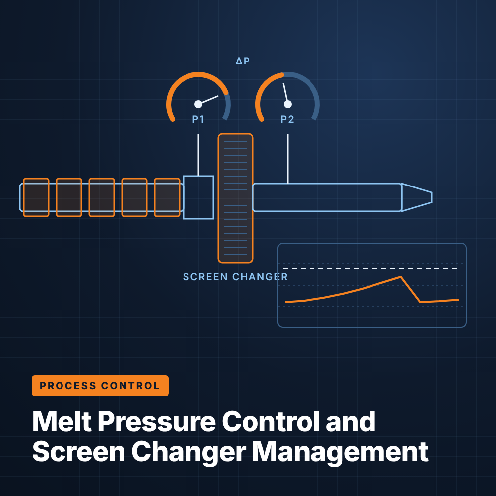
Most lines measure pressure at the end of the barrel, ahead of the screen changer, because this point shows the head pressure the screw must generate and is the primary input for overpressure protection. A second transducer after the screen changer allows the system to calculate differential pressure across the screen pack. Lines with a melt pump add transducers at the pump inlet and outlet, and some die systems include a transducer at the adapter or die body to monitor the pressure actually reaching the tooling.
Melt pressure transducers are typically filled-capillary or similar designs with a flush diaphragm that contacts the polymer. The mounting port must be machined correctly so the diaphragm sits flush with the flow channel; a recessed tip can trap degraded material and give a slow or inaccurate reading, while an improperly sized port can damage the sensor during installation.
On the electrical side, the excitation and signal wiring should be shielded and routed away from drive output cables. Periodic zero and span calibration, done at operating temperature, keeps the reading trustworthy enough to base control and safety decisions on it.
Holding melt pressure steady stabilizes output, which in turn stabilizes dimensions and gauge downstream. There are two common ways to do this, and the right choice depends on the line configuration.
On lines without a melt pump, the control system can trim extruder screw speed to hold a pressure setpoint at the die or after the screen changer. A PID loop compares measured pressure to setpoint and adjusts the drive speed reference. Because pressure responds quickly to screw speed but can be noisy, the loop usually needs filtering on the measurement and conservative gains to avoid hunting.
This approach works well when the main disturbance is a gradual pressure rise from screen loading. It is less ideal when the material feeds inconsistently, because chasing pressure with screw speed can amplify surging rather than damp it. Many systems therefore clamp how far the loop can move screw speed.
When a gear pump sits between the extruder and the die, the pump becomes the volumetric metering device, and the extruder's job is simply to keep the pump inlet supplied at a stable pressure. The control system holds pump speed constant to set throughput, while a PID loop adjusts extruder screw speed to maintain the pump inlet pressure setpoint. This decouples output from screw behavior and is common on film, sheet and precision profile lines.
The inlet pressure setpoint must be high enough to fill the gear teeth completely but not so high that it wastes energy or raises melt temperature. Too low, and the pump starves and output becomes unstable; too high, and the extruder works harder than necessary.
Screen packs filter contamination and gels from the melt, but they also add a restriction that grows over time. Managing that restriction is where pressure measurement and screen changer design meet.
As a screen pack captures contaminants, the pressure drop across it increases. Monitoring the difference between the pre-screen and post-screen transducers gives a direct measure of screen loading that is independent of throughput changes elsewhere in the line. Trending this value shows how quickly screens are blinding, which in turn reflects resin cleanliness, regrind content and filler dispersion.
Setting a differential pressure alarm, rather than relying only on head pressure, lets the control system prompt a screen change at a consistent point. A sudden jump in differential pressure can indicate a slug of contamination, while a drop may point to a ruptured screen that is no longer filtering.
Manual and hydraulic slide-plate changers move a fresh screen into the flow path in a single stroke. They are simple and robust but interrupt flow briefly and introduce an air pocket and a pressure disturbance as the new, empty cavity fills. That disturbance can show up as a gauge or diameter excursion and sometimes as a short run of scrap.
Control strategies can soften the event. Some systems temporarily hold screw speed or switch the pressure loop to manual during the change, then return to automatic once the pressure settles.
Continuous screen changers, such as rotary or belt designs, advance clean screen area into the flow gradually, either on a timer or based on differential pressure. Because the change happens in small increments, pressure stays far more stable, which suits lines with high contamination loads or tight dimensional tolerances. The trade-off is higher equipment cost and more complex mechanical maintenance.
Even with continuous changers, the control system should watch for pressure spikes during indexing. Tying the changer's advance logic to measured differential pressure keeps screen usage efficient and avoids changing screens either too early or too late.
Extruders can generate enough pressure to damage barrels, adapters and dies if flow is blocked. Protection is layered, with the control system acting first and mechanical devices as the last line of defense.
The primary protection is a high-pressure interlock in the control system. A warning alarm alerts operators as pressure approaches the limit, and a high-high setpoint trips the extruder drive if pressure keeps rising. Common causes include a cold die at startup, a blinded screen or a frozen plug in the adapter. Startup permissives that block screw rotation until all zones reach setpoint and soak reduce this risk.
The trip should act directly on the drive, not just on a speed reference, and should be independent of operator acknowledgment. Many plants also use a dedicated pressure switch or safety relay so that protection does not depend solely on PLC logic. Interlocks should be tested periodically, since a trip that has never been verified cannot be assumed to work.
A rupture disk is a mechanical burst device installed in the barrel or adapter that opens at a rated pressure to vent melt and relieve the system. It requires no power or logic, which makes it a reliable backstop if the electronic interlock fails. The disk rating must match the equipment's design limits and sit above the electronic trip setpoint so it only operates when the interlock has not.
Rupture disks should be installed with a guard or directed discharge so released melt does not endanger personnel. After a disk bursts, the root cause should be investigated before restarting, since it means the electronic protection either failed or was bypassed.
Older lines often have pressure readouts and trips that were added piecemeal, with limited trending and no integration between the screen changer and the main control system. Reviewing these systems can reveal both quality and safety gaps.
Modernizing the PLC and HMI makes it practical to add pressure loops, differential pressure alarms, trending and properly engineered interlocks without rebuilding mechanical equipment. Integrated Control Technologies works with extrusion plants on these upgrades, and its extruder control systems page describes how pressure control, screen changer coordination and safety logic fit into a unified platform.
At minimum, one transducer should sit at the end of the barrel ahead of the screen changer for control and overpressure protection. Adding a second after the screen pack allows differential pressure monitoring, and lines with melt pumps should measure pump inlet pressure as well.
Both work, but a melt pump provides more precise volumetric output because it decouples throughput from screw behavior. Screw speed control is a reasonable option on lines without a pump, especially when the main disturbance is gradual screen loading.
It indicates the screens are capturing contaminants and becoming restricted. A steady rise is normal and signals when to change screens, while a sudden jump or drop suggests a contamination slug or a damaged screen.
No, a rupture disk is a last-resort mechanical backstop. The primary protection should be a control-system interlock that trips the drive before pressure reaches the disk rating, with the disk rated above that trip setpoint.