Discover how advanced control systems improve product consistency, reduce waste, and optimize your extrusion process. Explore our solutions or connect with our team to learn how ICT can modernize your production line.
Get Started TodayAn extrusion line is a chain of machines that all handle the same continuous strand of product, whether that is film, sheet, tubing, cable jacket or a profile. If the extruder, puller and winder do not move in a fixed relationship, the product stretches, sags, wanders in gauge or winds into a roll that cannot be used. Synchronization is the control strategy that keeps every section working from a common reference. This article explains how that reference is generated, verified and maintained through starts, stops and roll changes.
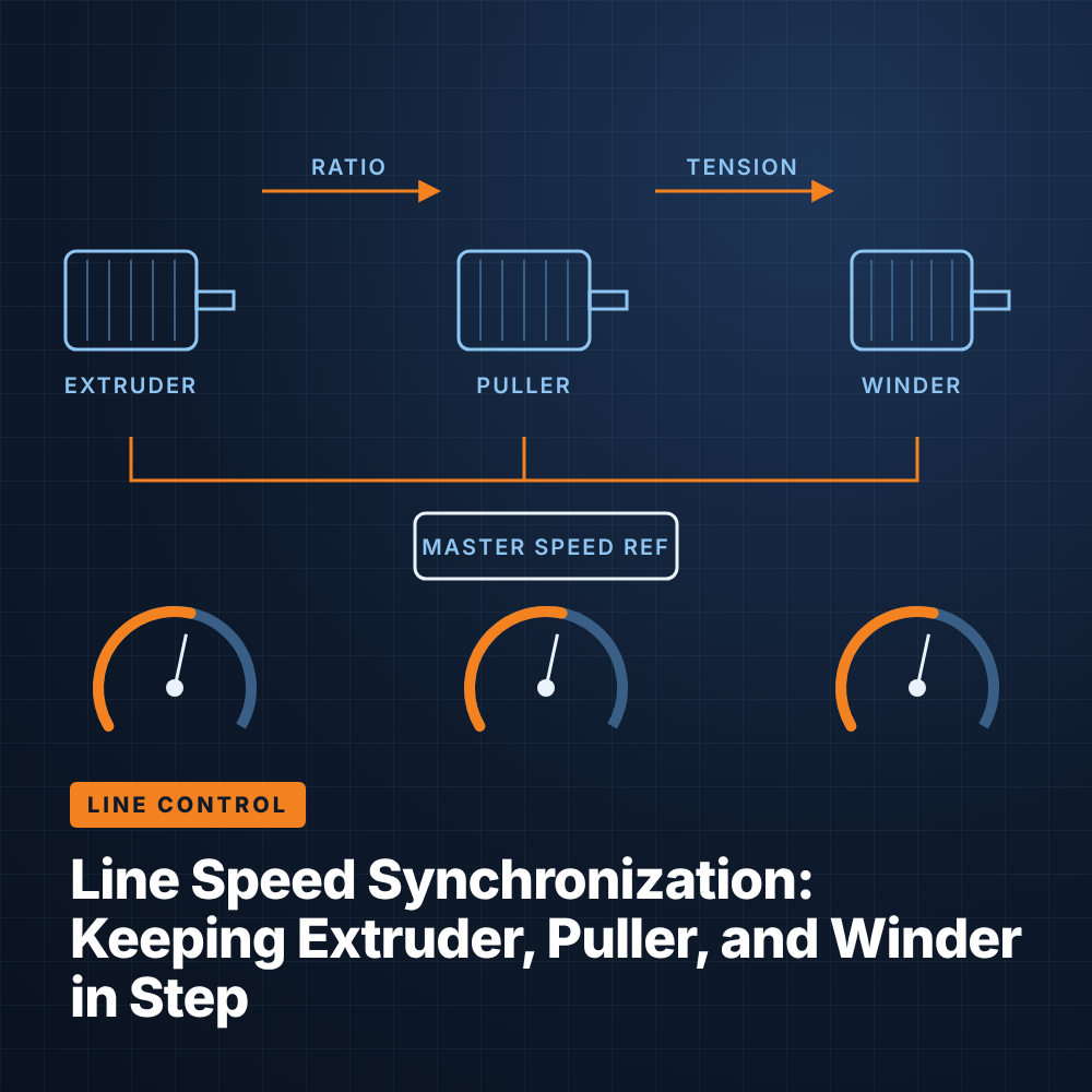
Most extrusion lines are built around a single master speed reference that every other drive follows. How that reference is chosen and applied determines how the line behaves when an operator makes a change.
On many lines the extruder is the natural master, because its output defines how much material is available downstream. Downstream drives then follow extruder speed at a set ratio. Other lines use a separate line speed setpoint as the master, with the extruder following to deliver the required throughput. Either approach works, provided every drive takes its reference from the same source rather than from independent operator setpoints.
The value of a master/follower structure is that one adjustment moves the whole line. When the master speeds up by a given percentage, every follower speeds up by the same percentage, so product dimensions and tension stay roughly where they were.
Ratio control expresses each follower's speed as a multiplier of the master. A puller set at a ratio of the extruder speed will always run in that proportion, which is useful when the relationship between screw speed and product speed is well understood.
Draw control expresses each section's speed relative to the section immediately upstream, usually as a small percentage difference. This is common between rolls in sheet lines, orientation stages and cable lines, where each section must run slightly faster than the one before it to maintain tension or stretch. Draw is intuitive for operators because a setting describes what happens to the product between two points. Many control systems support both: ratio from the master to the first section, then draw between subsequent sections.
A follower can only hold its ratio if it actually runs at the commanded speed. Open-loop drives estimate motor speed from electrical quantities and will drift as load, temperature and motor condition change. An encoder on the motor shaft lets the drive regulate speed in closed loop, holding speed tightly regardless of load.
For applications where slip is possible, such as belt pullers or nip rolls, a second encoder or measuring wheel on the product itself can confirm true line speed. The control system can then compare motor speed with product speed and alarm on slip, or use product speed as the reference for downstream functions such as cutting and length counting.
Synchronization is easiest to hold at steady state. The real test comes during acceleration and deceleration, when drives with different inertias and loads must change speed at exactly the same rate.
If each drive has its own acceleration ramp, the ratios between them break down during every speed change. A puller with a light load may reach its new speed well before a winder carrying a heavy roll, pulling the web tight or letting it go slack. The correct approach applies one ramp to the master reference, so that followers receive a reference that is already ramping. Each follower drive's internal ramp is then set faster than the line ramp so that it never becomes the limiting element.
High-inertia sections such as large winders may also need inertia compensation. The control system adds a torque feed-forward proportional to acceleration, so the drive supplies the extra torque needed to accelerate the roll instead of waiting for a speed error to develop.
A normal stop should ramp the whole line down together on the master reference, maintaining tension until zero speed. Emergency stops are more difficult because each drive may coast or brake differently. Well-designed safety logic considers what happens to the product as well as personnel, using coordinated fast stops where the safety assessment allows rather than simply dropping all drive power at once.
Threading a new product through the line usually happens at low speed with individual sections jogged by hand. The control system should make it easy to move from thread-up into synchronized operation, bringing sections into ratio before ramping to production speed.
The winder is different from every other section on the line because its roll diameter changes continuously. Holding constant surface speed and tension requires the drive to change its rotational speed and torque as the roll builds.
As a roll grows, the winder must slow its rotation to keep surface speed matched to the line. If it simply followed a fixed speed ratio, tension would rise steadily as diameter increased. Winder controls therefore calculate or measure roll diameter and adjust speed accordingly, while a tension loop corrects for any remaining error.
A dancer is a weighted or pneumatically loaded roller that rides on the web. Its loading sets tension, and its position indicates whether the winder is running too fast or too slow. The control system uses a PID loop to trim winder speed and keep the dancer centered.
Where a dancer is impractical, load cells under an idler roll measure tension directly, and the winder operates in torque or tension mode. Many products also benefit from taper tension, where tension is reduced gradually as diameter grows. Taper prevents the outer wraps from crushing the inner wraps, which helps avoid telescoping, blocking and gauge bands in film rolls.
How the speed reference travels from the controller to each drive affects how accurately the line stays in step. Older lines rely on analog signals, while newer systems use industrial networks.
A 0–10 V or 4–20 mA reference is simple and widely understood, but it has inherent weaknesses. Electrical noise from drives and heaters can couple into signal wiring, small offsets accumulate in each conversion, and the resolution of older analog cards limits how finely a ratio can be set. Calibration also drifts over time.
Industrial Ethernet and fieldbus protocols send speed references as digital values, eliminating noise pickup and conversion error. The same connection carries actual speed, current, torque, fault codes and diagnostic data back to the PLC and HMI. That visibility makes it far easier to trend a follower against its reference, catch slip or overload early, and troubleshoot a fault without opening a cabinet.
Networked drives also simplify changes. Ratios, draw settings, ramp rates and tension parameters can live in the PLC recipe and download to drives automatically, rather than being set with potentiometers or keypad parameters on each unit.
Many lines that struggle with gauge variation, tension upsets or poor roll quality are fighting their speed control system rather than their process. A structured review can identify where synchronization breaks down.
A practical evaluation looks at a few areas:
Synchronization improvements often come together with drive replacements, particularly when converting older DC drives to AC. Integrated Control Technologies builds coordinated extruder, puller and winder control into its extruder control systems, and the same principles apply to any well-engineered upgrade: one master reference, closed-loop followers and networked communication.
Ratio control sets each follower's speed as a multiple of the master reference. Draw control sets each section's speed as a small percentage difference from the section just upstream. Many lines use ratio from the extruder to the first downstream section and draw between later sections.
Not always, but drives that directly affect product dimensions or tension benefit significantly from closed-loop encoder feedback. Pullers, nip rolls and winders are common candidates. Less critical auxiliaries can often run open loop without affecting quality.
Dancers work well where there is room for the roller and some web storage is useful for absorbing disturbances. Load cells suit lines with limited space, very stiff products or applications that need a direct tension reading. Both can deliver good results when paired with diameter compensation.
Some existing drives accept a network communication card, which allows the reference to move to a digital network without full replacement. Older drives, especially legacy DC units, may not support modern networks, in which case a drive upgrade is usually the more practical path.