Discover how advanced control systems improve product consistency, reduce waste, and optimize your extrusion process. Explore our solutions or connect with our team to learn how ICT can modernize your production line.
Get Started TodayA profile leaves the die as a soft, oversized shape, and everything downstream determines whether it ends up as a part that fits a window frame, a fence rail or a medical channel. The relationship between how fast the extruder pushes material and how fast the puller draws it away sets wall thickness and overall size. Startup conditions decide whether the screw, die and tooling survive long enough to make good parts at all. This article walks through the control mechanisms that tie those pieces together and what to look for when a profile line struggles to hold dimensions.
In profile extrusion, the puller is not just a conveyor. It is a dimensional control element, and its speed relative to extruder output is one of the strongest levers an operator has over the finished part.
Draw-down ratio describes how much the extrudate is stretched between the die exit and the point where it is frozen into shape. A die opening is typically cut larger than the final profile, and the puller draws the melt down to size as it cools in the calibrator. A modest, stable draw-down helps orient the material and pull out minor die swell. Too much draw-down thins walls, distorts corners and builds in stresses that show up later as warpage or shrinkage in the field.
Conservation of mass makes the relationship straightforward in principle. For a fixed extruder output, the cross-sectional area of the finished profile is inversely proportional to the line speed. If the puller speeds up while extruder output holds steady, walls get thinner and weight per foot drops. If the puller slows or slips, material piles up and the profile goes heavy and oversized.
In practice, puller performance depends on belt or caterpillar grip, track pressure and the drive's ability to hold speed under varying load. A puller drive running open loop, or one with a worn tachometer, can drift without anyone noticing until parts start failing gauge checks.
The most robust approach treats the extruder as the master and the puller as a follower running at a set ratio. When an operator adjusts screw speed to increase throughput, the puller tracks proportionally and the draw-down stays constant. Fine trim on the puller ratio then becomes the tool for adjusting dimensions, rather than chasing two independent setpoints.
Some lines add a weight-per-length loop on top of this ratio, trimming screw speed or puller ratio to hold mass per foot. Because the underlying ratio keeps both machines moving together, the outer loop only has to correct small errors.
Many of the most expensive failures on an extrusion line happen in the first few minutes after a cold start. Startup interlocks exist to prevent the screw from turning against material that is not yet ready to flow.
Rigid PVC, filled compounds and engineering resins can be extremely stiff when they are below processing temperature. If the screw is rotated against a partially frozen plug in the barrel or die, torque climbs rapidly. The result can be a sheared screw shank, a damaged thrust bearing, a cracked gearbox tooth or a blown rupture disk.
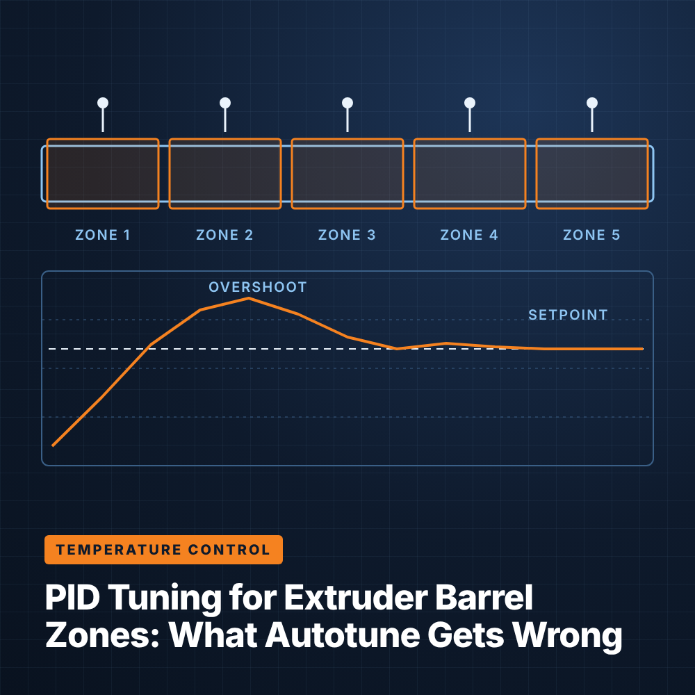
A minimum temperature interlock prevents screw rotation until every relevant zone, including the die and adapter, has reached its permissive setpoint. Well-designed logic monitors each zone individually instead of relying on an average, because a single cold die zone is enough to block flow. It should also block screw start if a thermocouple reads open or out of range.
Reaching setpoint on a thermocouple does not mean the steel around it is uniformly hot. Barrel and die thermocouples sit at a fixed depth, and the mass of a large profile die can lag well behind the reading. A heat-soak timer holds the permissive off for a defined period after every zone reaches temperature, giving heat time to conduct through the steel and into any residual material.
Soak time should be set by material and tooling rather than as a single plant-wide value. A small die running polyethylene needs far less soak than a large multi-cavity PVC die.
Once the permissive clears, the screw should start at a low speed and ramp up gradually. A drive current limit or torque limit set appropriately for startup provides a final layer of protection, tripping or holding speed if torque rises abnormally. Pairing this with a melt pressure high limit before the die catches restrictions that the temperature interlock cannot see, such as a blocked screen pack or a closed die adjustment.
After the die, the profile passes through vacuum calibration and cooling before reaching the cutter. Each of these stages interacts with puller speed and needs its own controlled setpoints.
Vacuum calibrators pull the hot profile against precision-machined sizing plates while water cools it. Vacuum level directly influences how well the outer surfaces conform to the calibrator, and therefore the final dimensions and surface finish. Too little vacuum lets walls sag or pull away; too much increases drag, which loads the puller and can cause chatter marks or stretching.
Treating vacuum as a monitored, alarmed variable rather than a manually set valve improves repeatability. Pressure transmitters on each calibrator zone, with deviation alarms and recipe-stored setpoints, help operators restore a known-good setup quickly after a changeover.
Flying saws and knife cutters must match profile speed during the cut, or they will produce angled ends, burrs or length variation. The cutter should take its speed reference from the puller, ideally through an encoder on the puller or a measuring wheel on the profile itself. Length is then counted against that encoder, so changes in line speed do not change cut length.
Many profiles combine materials: a rigid body with a flexible seal, a capstock over a recycled core, or a colored stripe. Each added extruder introduces another speed that has to stay in proportion.
In a co-extruded profile, the main extruder sets the base output and one or more satellite extruders feed secondary layers or features. Each satellite should follow the main extruder in ratio so that a change in overall throughput keeps the layer proportions constant. If a capstock extruder does not track, cap thickness drifts, which can affect weathering performance or appearance.
Multi-material lines need coordinated startup logic. Every extruder should satisfy its own temperature and soak permissives before any screw turns, and the start sequence should bring extruders online in an order that avoids forcing one material back into another's flow channel. A common sequence includes these steps:
Dimensional problems on profile lines are often blamed on tooling or material, but older control systems are frequently a contributing factor. A practical evaluation looks at how the machines communicate and protect themselves.
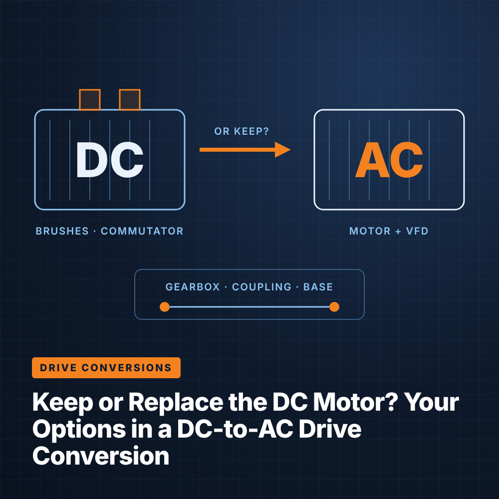
Common indicators include puller speed that drifts independently of extruder speed, setpoints that operators must re-enter manually for every product, cutters that run on timers, and startup procedures that depend on an operator remembering to wait. Noisy analog references and worn DC drive feedback can also add speed variation.
A well-integrated system ties the extruders, puller and cutter to a common speed reference, enforces temperature and soak permissives in logic, and stores complete recipes, including ratios, vacuum setpoints and soak times. Integrated Control Technologies works with profile processors on these upgrades; details on its approach are available on the profile extrusion solutions page.
There is no single value, because the right draw-down depends on material, profile geometry and die design. Most profile processes use relatively modest draw-down compared with film or fiber, since excessive stretching distorts complex shapes and builds in stress. The die designer and process engineer usually set the target together during tooling trials.
When the puller follows the extruder in ratio, any change in screw speed automatically produces a matching change in line speed, keeping draw-down and wall thickness constant. Independent setpoints require operators to adjust both machines by hand, which increases the chance of dimensional drift. Ratio control also makes startups and speed changes smoother.
Soak time depends on die mass, material and how cold the line was before startup. Large dies running rigid or heat-sensitive materials need longer soaks than small dies running polyolefins. Storing soak time in the product recipe lets each job load an appropriate value automatically.
In many cases, yes. The mechanical extruder, puller and downstream equipment can often stay in place while drives, PLC logic, HMI and speed references are modernized. A site evaluation determines which components can be retained and which need replacement.